USING AN AUTOMOTIVE TYPE RELAY TO CONTROL A NEMO PUMP:
Automotive type relays, commonly rated 30 Amps @ 12 Volt DC, can also be used to control other types of 12VDC loads…including 12VDC pumps. The main purpose of connecting a relay into a water pump control circuit, is that the relay will enable the water pump to be turned on and off from a distant, remotely located, holding-tank-mounted float switch. The advantage of using a relay is that the float switch would require a much lighter gauge (and thus less expensive) run of wire to operate the (very low amp draw) relay than the heavier gauge run of wire required if the float switch were wired directly into the circuit that runs the (much higher amp draw) pump.
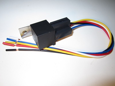
OVERVIEW OF COMMON AUTOMOTIVE TYPE RELAY:
Relays are widely used in electrical applications when a large current/voltage needs to be switched on and off by a low power control circuit.
The diagrams below are a schematic representation of a standard automotive relay as originally designed by Bosch. Pins 85 and 86 are the connections for the electromagnet coil. One will be grounded and the other connected to 12 volts. Either pin can be wired through a mechanical switch.
Pins 87, 87a, and 30 are the connections for the switch contacts, and are generally rated for at least 30 amps. This switch is a single pole, double throw type, or SPDT. Pin 30 is the “pole”, which can “throw” to either of the other two contacts. In its normal state, the pole is connected to pin 87a. When energized, the relay toggles so that the connection is broken between the pole and 87a and completed to pin 87. So depending upon how the switch is wired, it can open an electrical circuit as easily as close the circuit!
The terminals of a relay are defined as follows:
30 is the pole or common.
87a is the normally closed connection.
87 is the normally open connection.
85 is connected to 12 volts or ground and may be switched.
86 is connected to 12 volts or ground and may be switched.
HOW TO WIRE A RELAY INTO A TYPICAL CIRCUIT OF A SOLAR POWERED, FLOAT SWITCH CONTROLLED PUMP:
Components: PV Module, Charge Control w/LVD, Battery, Pump, Relay, Float Switch.
1. Connect wires from the PV (+/-) terminals to the “SOLAR” (+/-) terminals on Charge Control.
2. Connect the (+) wire from pump to the “LOAD” (+) terminal on Charge Control and connect the (-) wire from Pump to terminal #87 on Relay.
3. Connect Relay terminals #30 and #85 to the “LOAD” (-) terminal of the Charge Control.
4. Connect one of the wires from the Float Switch to the “LOAD” (+) terminal of the Charge Control, and connect the other wire from the Float Switch to the #86 terminal of the Relay (Relay terminal #87A is not used in this application).
$10 WORLDWIDE ONLY IF ORDERED WITH A PUMP.